To address this, I developed a simplified mechanical model of the disk--bolt--cable system to quantify the relationship between applied cable force, disk radius, and resulting bolt stresses. By treating the disk as a rigid body with reaction forces localized at the bolt interfaces and enforcing equilibrium under applied torque, I derived allowable force limits based on bolt material yield strength and cross-sectional properties. This analysis produced a safe operating force range for manual actuation, eliminating plastic deformation while preserving reliable indexing. The result was a mechanically bounded system with defined load constraints, transforming an empirical failure into a controlled, analytically governed design parameter.
Impact (slam) speed limit
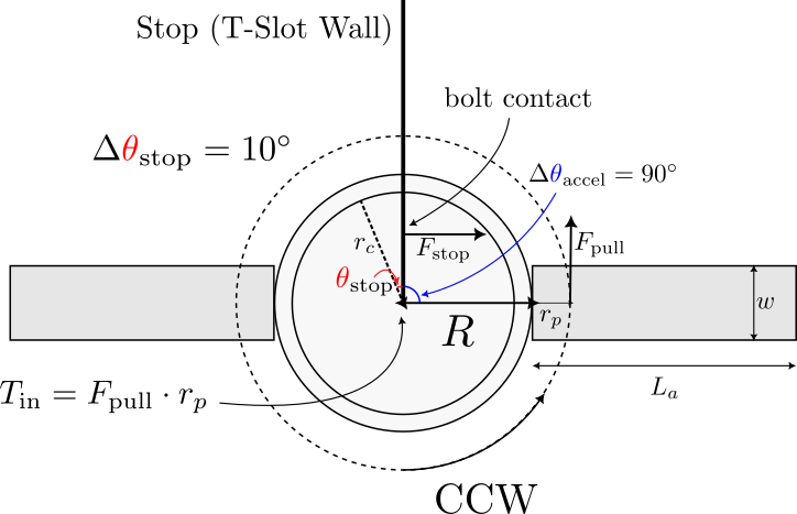
Assume one bolt takes the full stop load (worst-case). If the disk impacts the stop at angular speed \(\omega\) (rad/s), the rotational kinetic energy is
\[
E_k=\frac{1}{2}\frac{I}{g_c}\,\omega^2,
\]
where \(I\) is the mass moment of inertia in \(\mathrm{lbm\cdot in^2}\) and \(g_c=386.09~\mathrm{\frac{lbm\cdot in}{lbf\cdot s^2}}\).
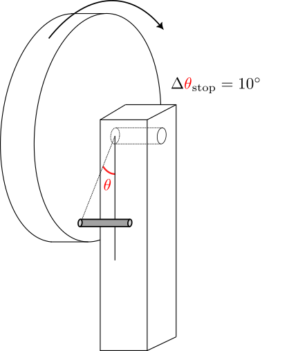
Assuming the stop dissipates this energy over the compliance angle \(\Delta\theta_{\text{stop}}\), and using a linear torque ramp \((T_{\text{peak}}\approx 2T_{\text{avg}})\),
\[
T_{\text{stop,peak}}\approx \frac{2E_k}{\Delta\theta_{\text{stop}}}.
\]
Convert peak stop torque to bolt bending stress (threads in bending):
\[
\sigma_{\text{bolt,peak}}
=
\frac{32}{\pi d_{\text{minor}}^3}
\left(\frac{T_{\text{stop,peak}}}{r_c}\right)
L_{\text{bolt,eff}}.
\]
Combining all terms gives a speed--stress relationship:
\[
\sigma_{\text{bolt,peak}}
=
\left(
\frac{
32 I L_{\text{bolt,eff}}
}{
\pi d_{\text{minor}}^3
\Delta\theta_{\text{stop}}
r_c
g_c
}
\right)\omega^2.
\]
Numerical evaluation
Using
\(I = 351.352~\mathrm{lbm\cdot in^2}\),
\(g_c = 386.09~\mathrm{\frac{lbm\cdot in}{lbf\cdot s^2}}\),
\(\Delta\theta_{\text{stop}}=\pi/18\),
\(r_c=3.75~\mathrm{in}\),
\(L_{\text{bolt,eff}}=2.75~\mathrm{in}\),
\(d_{\text{minor}}=0.19~\mathrm{in}\),
the stress law reduces to
\[
\sigma_{\text{bolt,peak}}
\approx
5678\,\omega^2~\mathrm{psi}
=
5.678\,\omega^2~\mathrm{ksi},
\qquad
(\omega \text{ in rad/s}).
\]
Grade 2 ''no-yield'' speed
Assume Grade 2 yield strength \(S_y \approx 57~\mathrm{ksi}\). If ``do not yield'' means \(\sigma_{\text{allow}}=57~\mathrm{ksi}\),
\[
57 = 5.678\,\omega^2
\quad\Rightarrow\quad
\omega_{\max}=3.17~\mathrm{rad/s}.
\]
Convert to RPM:
\[
N_{\max}
=
\omega_{\max}\frac{60}{2\pi}
=
30.3~\mathrm{rpm}.
\]
\[
\boxed{N_{\max}\approx 30~\text{rpm at the moment of impact}.}
\]
Recommended engineering limits (with safety factor)
If instead \(\sigma_{\text{allow}}=\frac{S_y}{n_y}\), then:
- For \(n_y=2\): \(N_{\max}\approx 21.4~\mathrm{rpm}\).
- For \(n_y=3\): \(N_{\max}\approx 17.5~\mathrm{rpm}\).
A conservative operating recommendation is therefore:
\[
\boxed{\text{Keep impact speed } \lesssim 17\text{--}20~\mathrm{rpm}.}
\]
\[
\boxed{20~\mathrm{rpm} \approx 0.333~\mathrm{rev/s}.}
\]
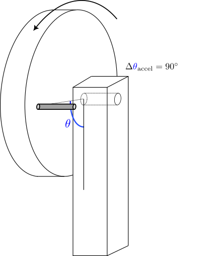
At \(20~\mathrm{rpm}\) (\(0.333~\mathrm{rev/s}\)), the disk rotates at about \(120^\circ/\mathrm{s}\). That means a \(90^\circ\) index move takes roughly \(t \approx 0.75~\mathrm{s}\) if you rotate at a steady rate. Practically, this is a “moderate” motion—fast enough that you should consciously slow down as you approach the hard stop, since bolt yielding is driven by the impact speed at contact (i.e., \(\omega\) right before the stop), not the average speed over the full rotation.